When electrical equipment fails in an industrial plant, the immediate response is almost always replacement. A breaker trips — it gets reset or swapped. A transformer fails — a spare is fitted and the plant restarts. The failure event is closed out. Except it isn’t.
Replacing failed equipment without identifying the root cause is not a corrective action. It is a deferral. The same failure conditions remain in the system. The same fault will recur — sometimes faster the second time, because the replacement equipment is new but the conditions that destroyed the original unit are unchanged.
Root cause electrical failure analysis is the structured engineering process that prevents this cycle. It determines not just what failed, but why, and what underlying system conditions made the failure possible. This post outlines the principal electrical failure analysis techniques used in industrial investigations, the standards that govern their application, and the factors that determine when each method is required.
What Is Electrical Failure Analysis and When Is It Required?
A formal investigation is distinct from a routine repair response. A repair addresses the symptom. An investigation addresses the cause.
Electrical failure analysis is a structured engineering investigation to determine the physical, electrical, and operational causes behind a component or system failure. It is required after any unexpected equipment failure, recurring protective device operation, or event that caused production loss, injury risk, or asset damage.
The distinction matters because many industrial electrical failures share contributing conditions — incorrect protection settings, deteriorated insulation, supply-side power quality anomalies, or fault current levels that exceed equipment ratings. Without investigation, none of these conditions are identified or corrected.
CEA Safety Regulations 2023 require that electrical installations, including protection systems, be maintained in correct working condition with documented settings and periodic verification.
Visual and Physical Inspection: The Starting Point of Any Investigation
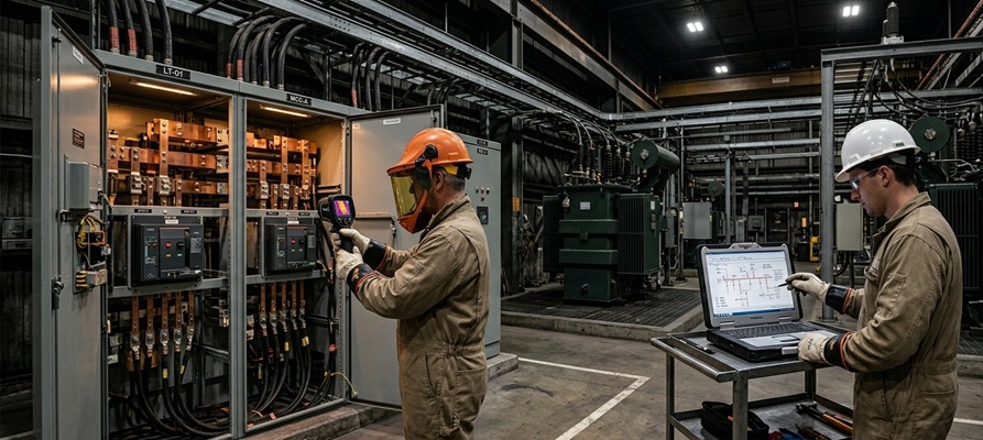
Before any instrument is connected and before any equipment is disturbed, a trained engineer documents the failure site as found. Visual and physical inspection identifies burn patterns, tracking marks on insulation surfaces, carbonisation at terminals, signs of sustained overheating at bus joints, mechanical damage, and evidence of moisture ingress or contamination.
Photographs taken before disturbance capture conditions that cannot be reconstructed after equipment has been removed or cleaned.
What Electrical Tests Are Used in Failure Analysis?
Electrical tests used in failure analysis include insulation resistance testing, polarisation index measurement, contact resistance measurement, hi-pot testing, and partial discharge detection. Each test targets a specific failure mechanism.
Insulation Resistance Testing
Insulation resistance (IR) testing applies a DC voltage across the insulation of a motor winding, cable, or transformer and measures the resistance of the insulating material. Low IR values indicate moisture ingress, contamination, or thermal degradation of the insulation.
Contact Resistance and Thermographic Measurement
High contact resistance at bus joints, cable terminations, and switchgear contacts generates localised heat. Over time, this thermal stress accelerates insulation degradation, loosens connections further, and in some cases initiates arc events. Thermographic scanning — conducted during live operation — detects temperature differentials that indicate high-resistance connections before they reach failure.
Partial Discharge Detection
For high-voltage equipment, partial discharge (PD) testing identifies discharges occurring within insulation voids, at conductor surfaces, or at contaminated interfaces. These discharges indicate progressive insulation degradation. PD activity may precede a failure event by weeks or months, and its detection can confirm whether insulation breakdown was the primary failure mechanism.
How Power Quality Measurement Supports Root Cause Identification
Power quality measurement identifies voltage fluctuations, harmonic distortion, transients, and unbalance conditions that may have caused or contributed to equipment failure. Without power quality data, an investigation cannot confirm or rule out supply-side conditions as contributing factors.
Several failure modes have power quality as their primary or contributing cause:
Thermal Stress on Insulation
Increase RMS current in motors and transformers, causing thermal stress that degrades insulation over time.
Negative Sequence Heating
Causes negative sequence currents in motor windings, generating heat disproportionate to the unbalance magnitude.
Overvoltage Stress on Insulation
Caused by capacitor switching, lightning, or nearby fault events — impose overvoltage stress on insulation that may initiate breakdown.
Motor Winding Overheating
Causes motors to draw higher current to maintain output, increasing winding temperature beyond rated limits.
Short Circuit and Fault Current Analysis in Failure Investigations
Equipment in an electrical distribution system is rated to interrupt or withstand fault currents up to a specified level. When fault current at the point of failure exceeds the equipment’s interrupting or withstand rating, the result is destructive failure — even if the equipment was correctly selected at the time of installation.
Short circuit analysis per IEC 60909 calculates fault currents at every bus in the system across operating modes. In a failure investigation, this calculation verifies whether the failed equipment was rated adequately for the fault current it encountered.
IEC 60909 — Governs short-circuit current calculation in AC systems. Provides the engineering basis for verifying equipment interrupting and withstand ratings against actual fault currents.
CEA Safety Regulations 2023 — Requires that protection systems and equipment ratings are maintained in correct working condition. Fault current verification is a core element of post-failure compliance review.
IEEE 1584-2018 — Uses fault current and clearance time as primary inputs to arc flash incident energy calculation — directly relevant when an arc flash event is under investigation.
Role of ETAP Simulation in Fault Current Reconstruction
ETAP simulation helps engineers recreate the actual system conditions present at the time of an electrical failure. It verifies fault current levels, protection device performance, relay coordination, and whether system changes since commissioning have affected equipment safety.
In multi-source industrial systems, operating conditions can vary significantly, and field testing alone may not reveal these risks. ETAP provides the engineering clarity needed to identify whether incorrect protection settings, changed system configurations, or equipment rating mismatches contributed to the failure.
Key Considerations: What a Credible Failure Investigation Should Cover
- Site documentation — Condition is recorded as found, before any equipment is disturbed or replaced, with photographs.
- Test results — Electrical test results are interpreted against applicable standard limits, not just pass/fail at the instrument’s default threshold.
- Power quality check — Power quality data is collected or sourced from plant records for the period preceding the failure.
- Fault current validation — Short circuit calculations are performed for operating modes active at the time of the failure.
- Corrective recommendations — Findings address immediate cause, underlying cause, and systemic cause — in a form suitable for regulatory reporting.
Get a Professional Assessment of Your System. If your facility has experienced an unexplained equipment failure or a recurring protective device operation, a structured Root Cause Electrical Failure Analysis determines whether your protection system and equipment ratings reflect your current system configuration.
Contact Us →Frequently Asked Questions
What is the difference between electrical failure analysis and an electrical safety audit?
Electrical failure analysis investigates a specific failure event to identify its root cause using test data, simulation, and site inspection. An electrical safety audit checks the overall safety, condition, and compliance of an installation against applicable standards. In simple terms, an audit identifies future risks, while failure analysis explains why a specific failure already happened.
What are the most common root causes of electrical equipment failure in industrial plants?
Common causes include insulation breakdown, moisture ingress, overloaded systems, incorrect protection settings, fault current levels exceeding equipment ratings, power quality issues like harmonics or voltage unbalance, and high-resistance cable terminations that create overheating. In many cases, system changes without protection review also lead to failures.
SAS Powertech is an independent electrical safety and power system engineering consultancy. Services include Electrical Safety Audits, Arc Flash Analysis, Relay Coordination, Short Circuit Analysis, Power Quality Audits, Load Flow Analysis, and Root Cause Electrical Failure Analysis.
Contact: info@saspowertech.com | +91-9763003222 / +91-9011028802 | 01 Gera's Regent Manor, Baner, Pune 411045
Get a Professional Assessment of Your System
If your facility has experienced an unexplained equipment failure or a recurring protective device operation, a structured Root Cause Electrical Failure Analysis determines whether your protection system and equipment ratings reflect your current system configuration.